Semester 01 Experiments
Introduction
Sound and Shape Experiment
As part of today's class session, we were
required to devise a simple experiment. I
was curious as to whether a Bluetooth
speaker will sound differently when placed
in different shaped structures. While I made
the shapes in class, I was unable to conduct
the experiment since I did not have my
speaker with me.
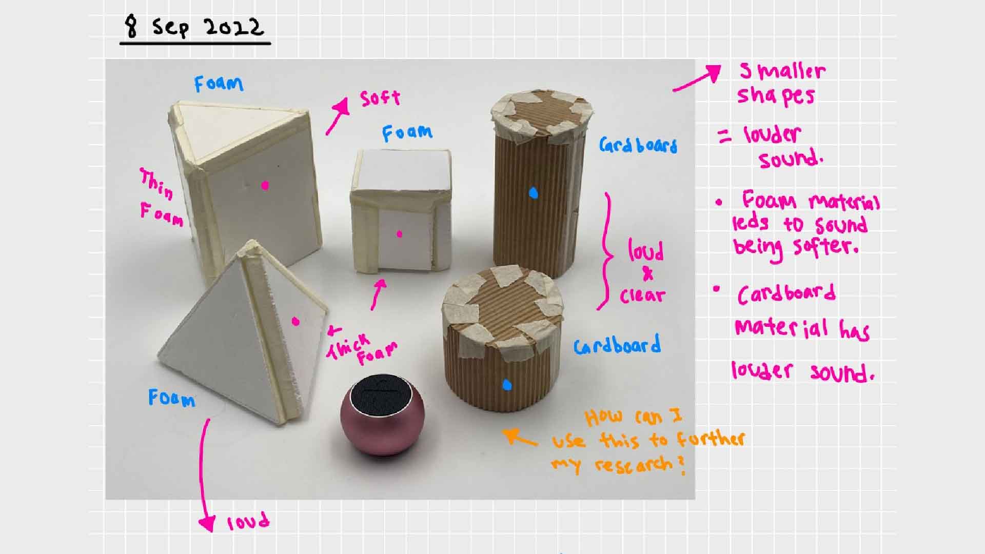
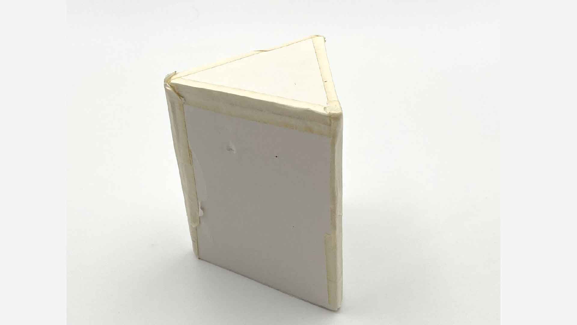
- Softest volume: big-triangle, -38.35 LUFS.
- Loudest volume: long-tube, -32.30 LUFS.
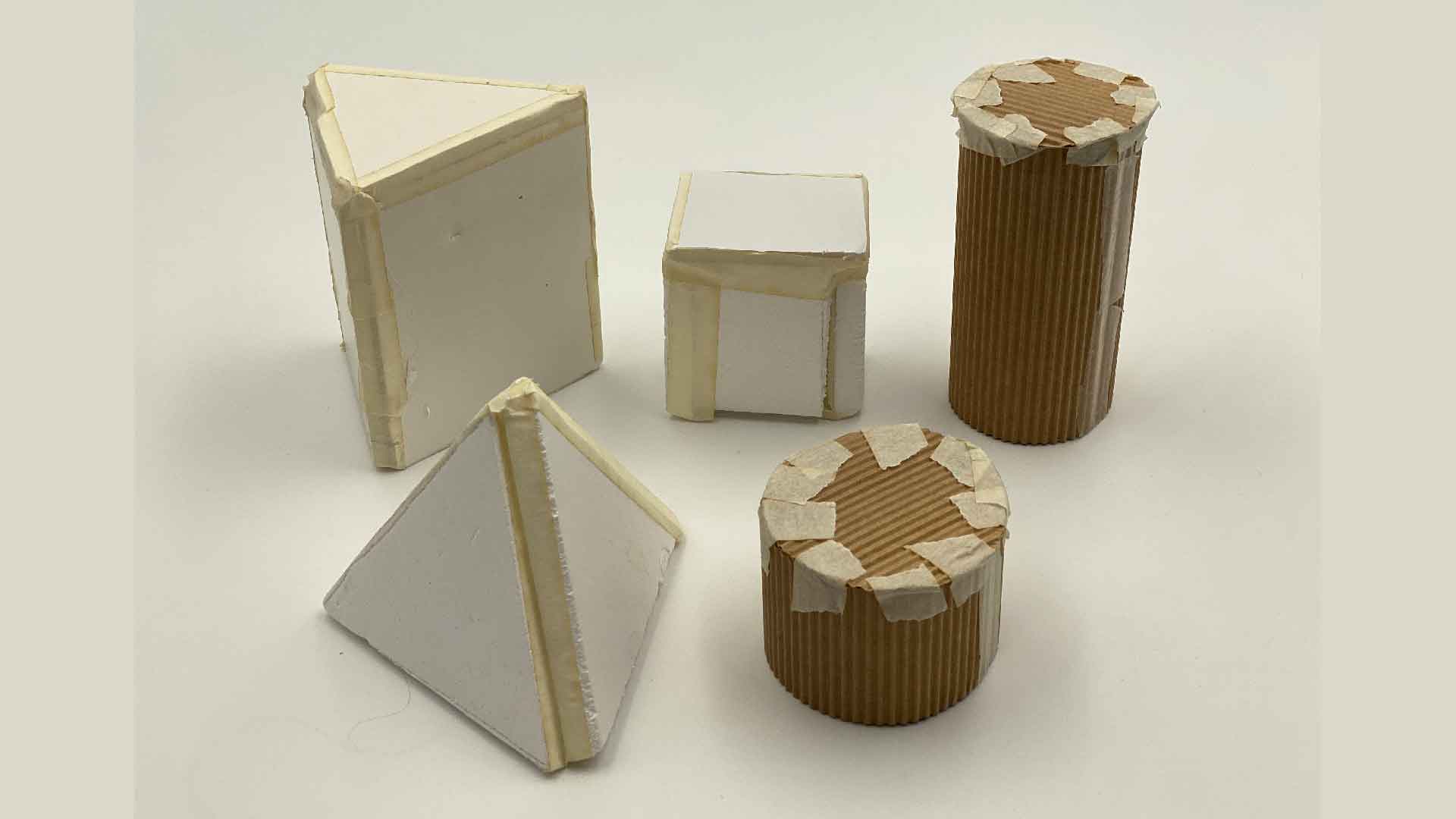
- Materials used in experiment: Cardboard and foam.
Reflection — Different variables
This experiment does not seem accurate
because different materials were used to
make the shapes. I used foam for the two
triangles and cube shape, and cardboard
for the tube shapes because it is less
sound insulating than foam. Another
example is that I did not seal the sides
of the tube shapes very well with the
masking tape. You can see some gaps in
between. I have chosen foam shapes for
my conclusion since they are the most
consistent shapes. As determined by
Adobe Audition, the loudest foam object
is the small triangle, while the largest
triangle shape has the softest audio
volume.
Observation Notes
Big Triangle Audio
Big Triangle Shape 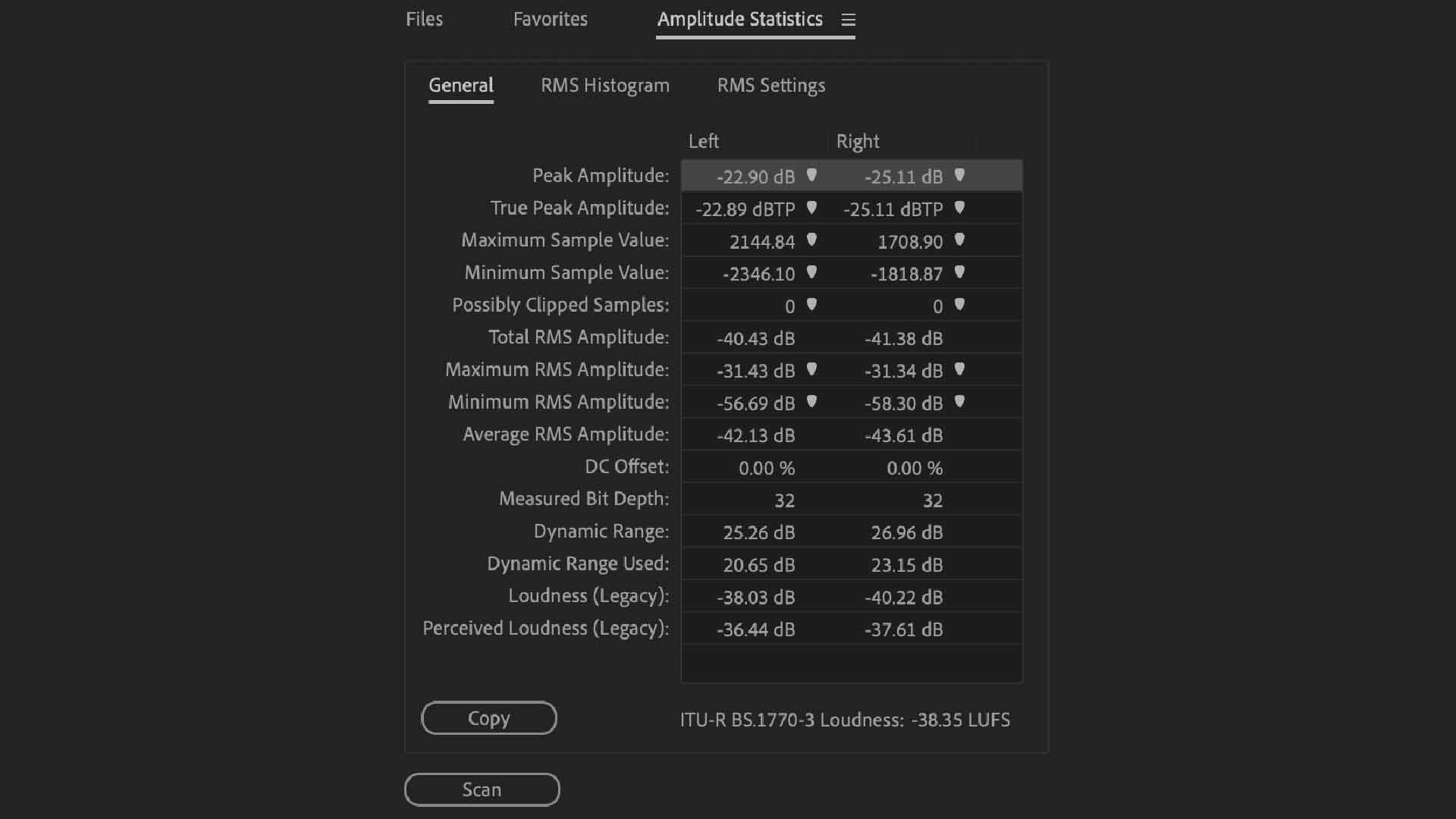
Big Triangle Audio Reading
Small Triangle Audio
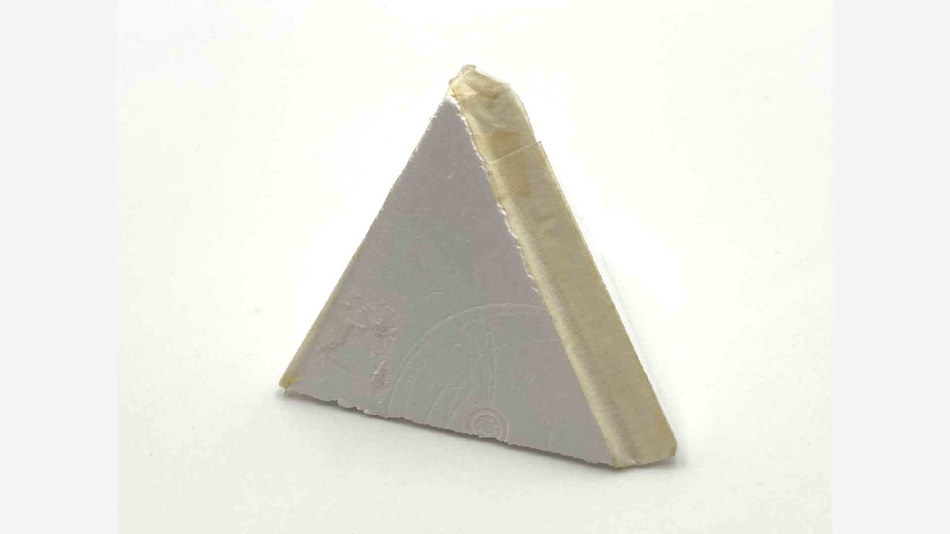
Small Triangle Shape 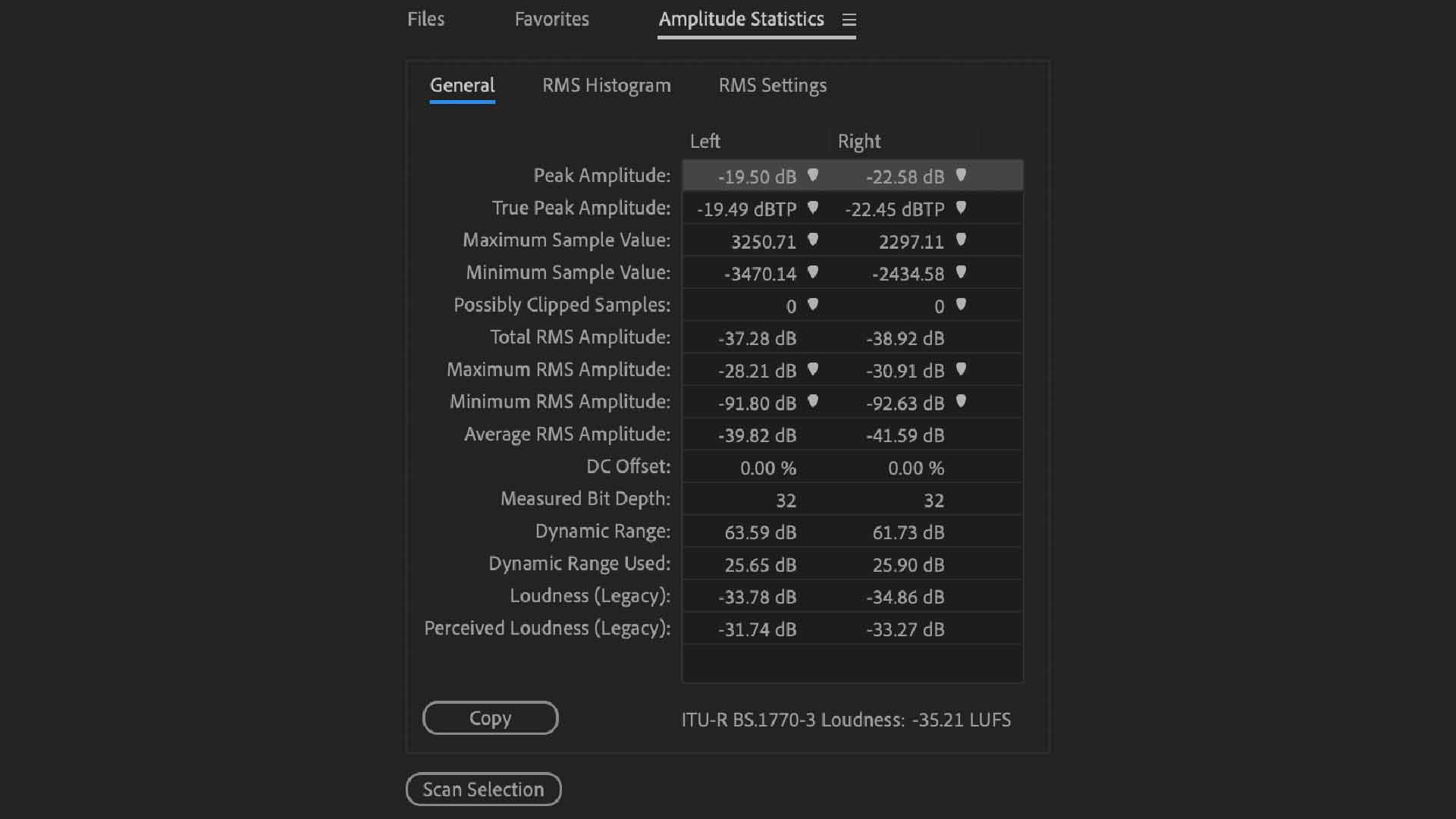
Small Triangle Audio Reading
Cube Audio
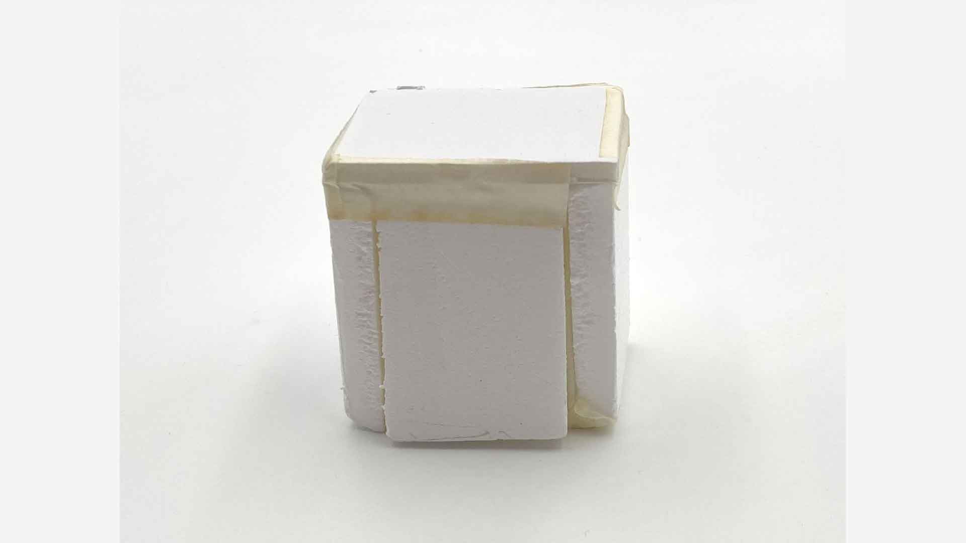
Cube Shape 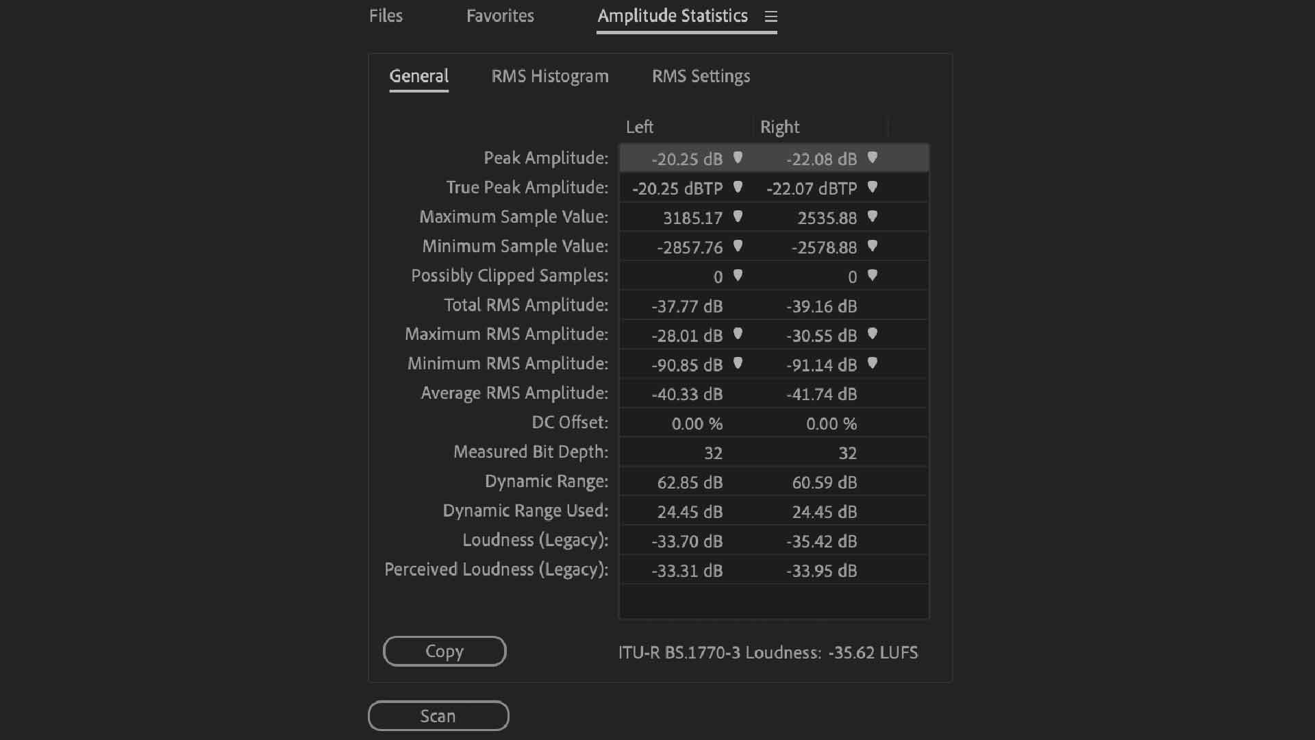
Cube Audio Reading
Long Tube Audio
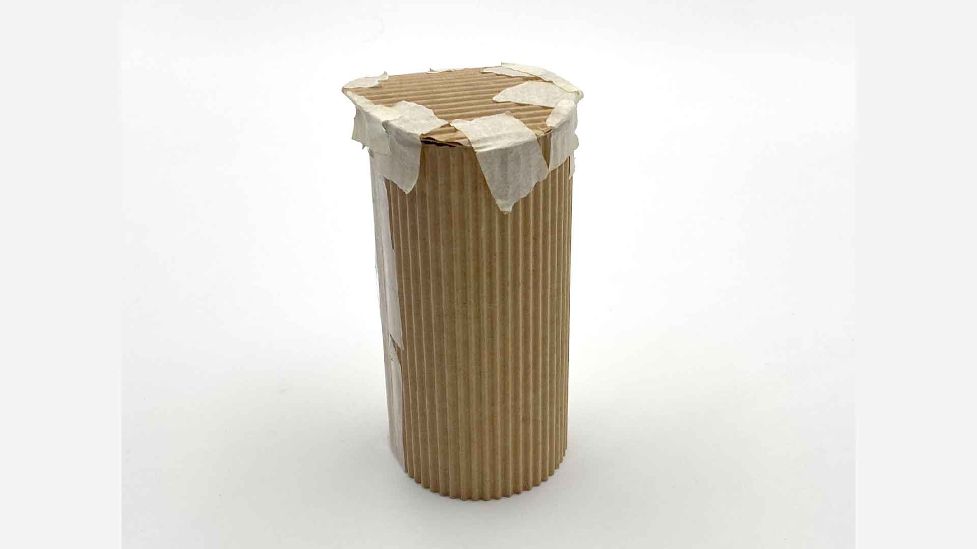
Long Tube Shape 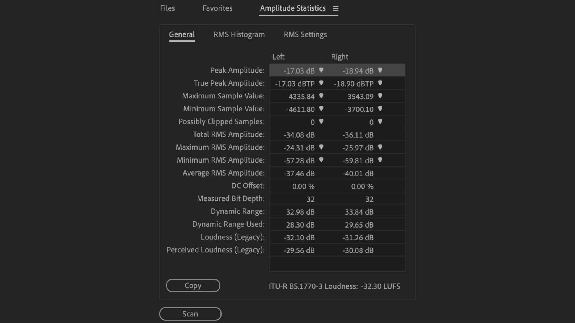
Long Tube Audio Reading
Short Tube Audio
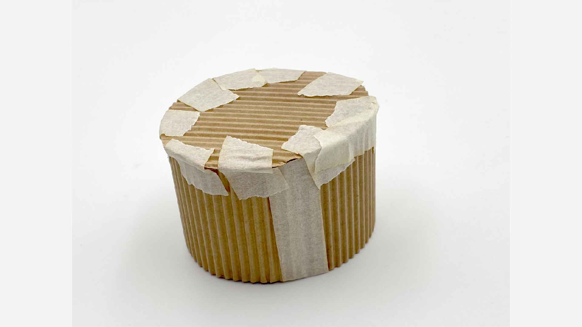
Short Tube Shape 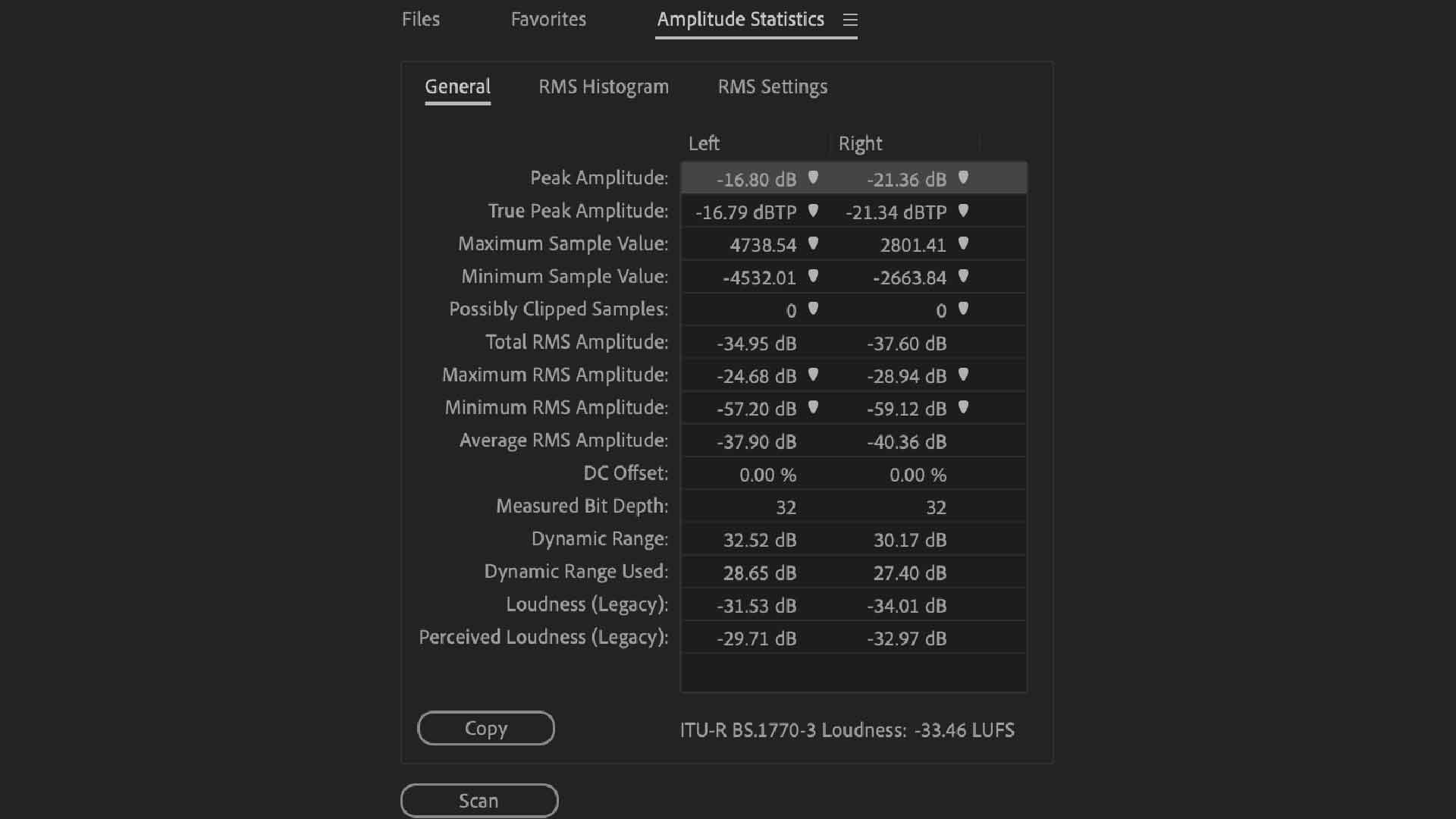
Short Tube Audio Reading
Noise floor level
Currently, I have conducted seven soundwalks and collected field recordings at different locations. A spreadsheet was used to organize the recordings by time and location. I collected data by counting the different sounds that I recorded. Because I was uncertain of my research topic, I chose a location based on the amount of human traffic. For example, Pasir Ris Beach contains recordings of animals, humans, and waves. Now that my research topic is confirmed to be urban noise. I felt like some recordings did not provide much insight because I did not actively search for signs of urban noise within the soundscape. I believe it would be best to conduct further soundwalks in an area where urban noise pollution is prevalent.
It was through reading a paper online entitled Designing with urban sound exploring methods for qualitative sound analysis of the built environment that I became acquainted with the concept of noise maps. This concept is referred to by the author as a method for determining an environment's soundscape quality. In most noise maps I have seen online, the different decibel level of the location is colour coded. As I am interested in displaying my field recordings visually, I considered this to be a useful experiment.
An article published online discusses Adobe Audition noise floor levels and how to measure them. According to the article, the noise floor is the amount of sound that does not originate from you during recording. Although noise floor is generally the result of the surrounding environment, it can also be a result of your audio recording equipment or signal interference from other devices.
CSV Spreadsheet for field recordings
| Time | lat | long | data |
| 2022-04-22-17-00 | 1.378574704 | 103.9513681 | 3 |
| 2022-08-27-15-00 | 1.373813566 | 103.9514608 | 1 |
| 2022-09-03-12-00 | 1.353333142 | 103.9403505 | 1 |
| 2022-09-04-10-00 | 1.378574704 | 103.9513681 | 3 |
| 2022-09-16-15-30 | 1.350958809 | 103.9513681 | 3 |
| 2022-09-17-13-15 | 1.282450627 | 103.8442651 | 4 |
| 2022-09-17-16-00 | 1.314054219 | 103.8158921 | 4 |
Electric Paint Sensor Experiment
In order to complete my research, I wish to create a physical artefact. I have researched two platforms on how I can use them to create a button interface. My choice was the Bare Conductive platform because it seemed more beginner-friendly. After I have become familiar with this current platform, I will explore the Arduino platform for my next experiment.
Bare Conductive Touch Board
While researching the platform, I
discovered that Bare Conductive,
which produces electric paint, also
produces the Touch Board, which is a
product that has a wide range of
functions and works well with their
electric paint. Using the Bare
Conductive microcontroller board,
you are able to create interactive
sensors from a variety of materials
and surfaces by utilising 12
capacitive touch and proximity
electrodes.
After looking through the different videos online, I discovered that using electric paint as a means of making buttons for my sound clips could be an interesting method, as I was able to create different shapes, sizes, and patterns by simply painting the surface. I also found the touch board interesting because it can make any conductive object act as a sensor.
As a first step, I needed to familiarise myself with the touch board, and I found a useful introductory guide on the Internet.
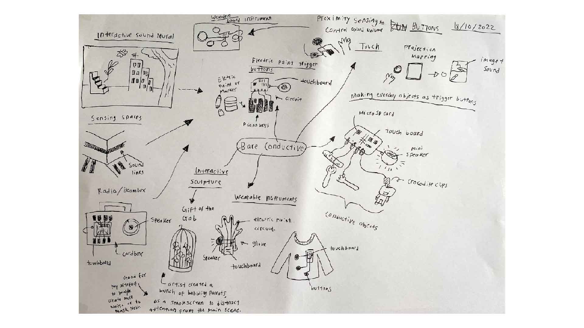
Mindmap Of Possible Artefacts
Step 01 — Audio Guide
It has twelve golden squares, which are electrodes that can be touched to trigger the different sounds from the storage card.
Step 02 — Audio Files
As part of this experiment, I selected five tracks that contain urban noises and seven tracks that contain soundscapes of the places I visited. These will not be the final audio tracks, but they are what I have available so far. I will need to record clearer forms of urban noises for future soundwalks in order to make the concept of sound pollution clearer. Audio tracks must be titled in a certain way in order for the Touch Board to read them.
- TRACK000.mp3
- TRACK001.mp3.
- TRACK002.mp3
- …up to TRACK011.mp3
- TRACK000.mp3 will be for E0
- TRACK001.mp3 will be for E1
- TRACK001.mp3 will be for E2
Since some of the audio clips were too long, I cropped them. So far, I have only been able to play different audio files using the electrodes; if you press another electrode, you will change the audio file that is currently playing. However, I have not yet been able to stop them from playing. Because there is no stop button, the audio files had to be shortened because it seems like the button only works one way.
During the playback of the audio files, some of them are too soft, as you can see in the video. Initially I thought the speakers would be able to adjust the volume, but the volume buttons do not work with the touch board. I must increase the volume. After researching online, I discovered that I can modify the touch board code using the Arduino software if I wish to change the volume.
The audio volume is increased when I change the values of the default MP3player.setVolume(10,10); to a lower value, but I am unsure how to change the volume of the individual files, as some audio files have a higher volume, so the single volume setting is ineffective.
Step 03 — Template
I spent a lot of time making a stencil, which I thought would help me produce clean straight lines. Initially, I printed my template on ordinary printer paper, but it was too thin for cutting out the shapes. I realised halfway through that the template size is incorrect because it is much larger than the touch board.
In order to get the circle connections correct, I attempted freehand drawing on thicker paper, but I failed because the size was so small.
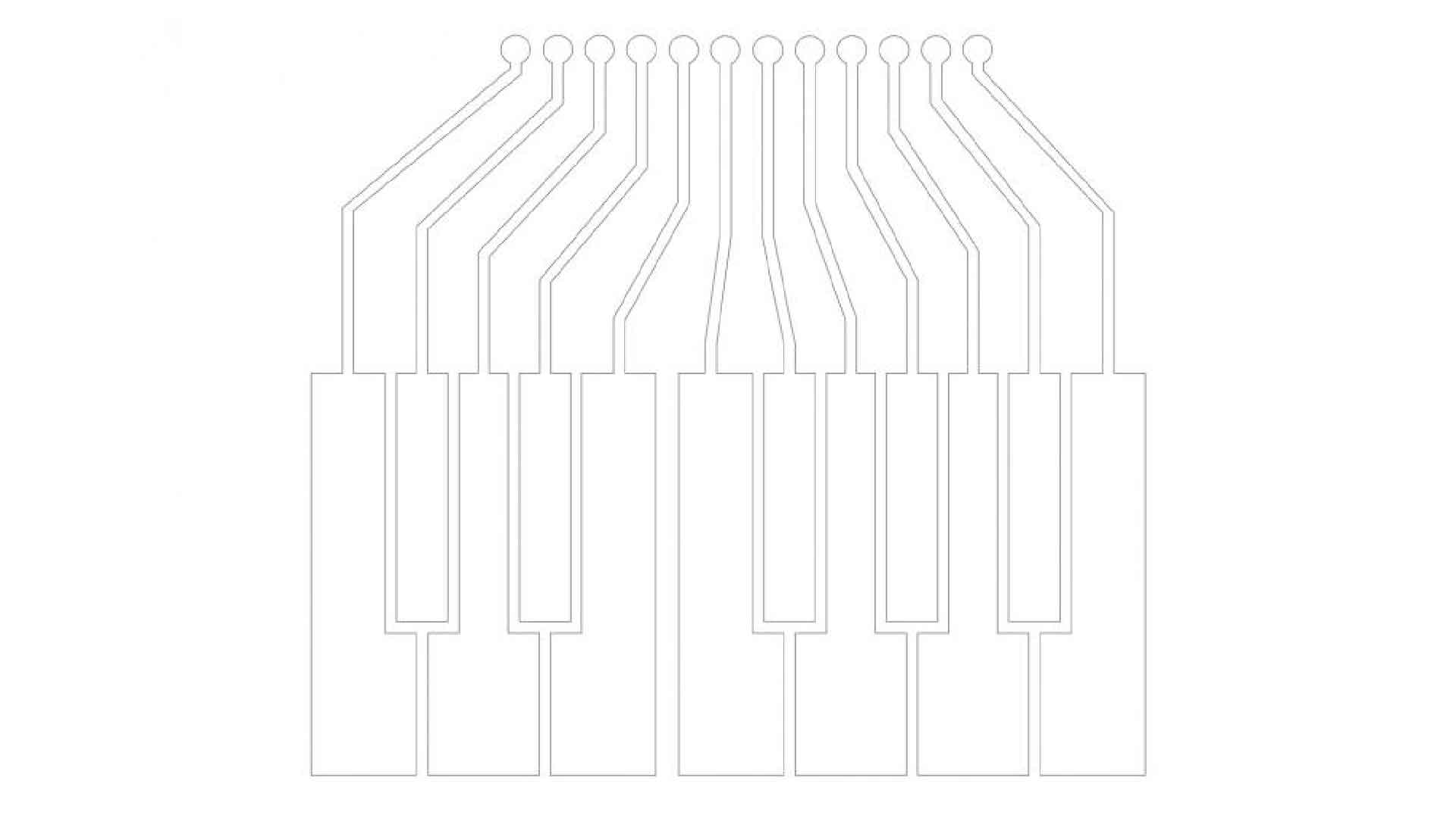
Online Template 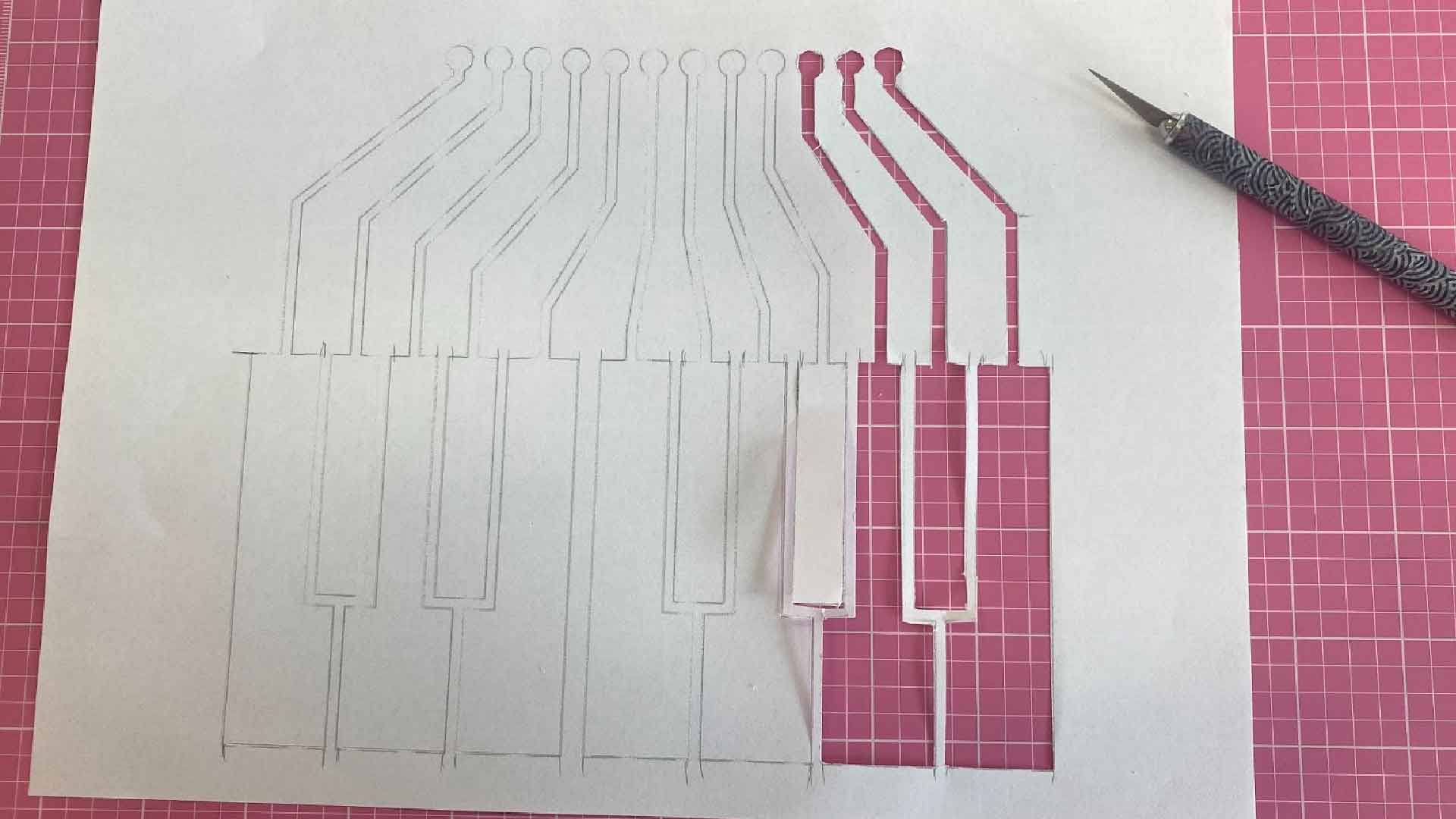
Wrong Template Size 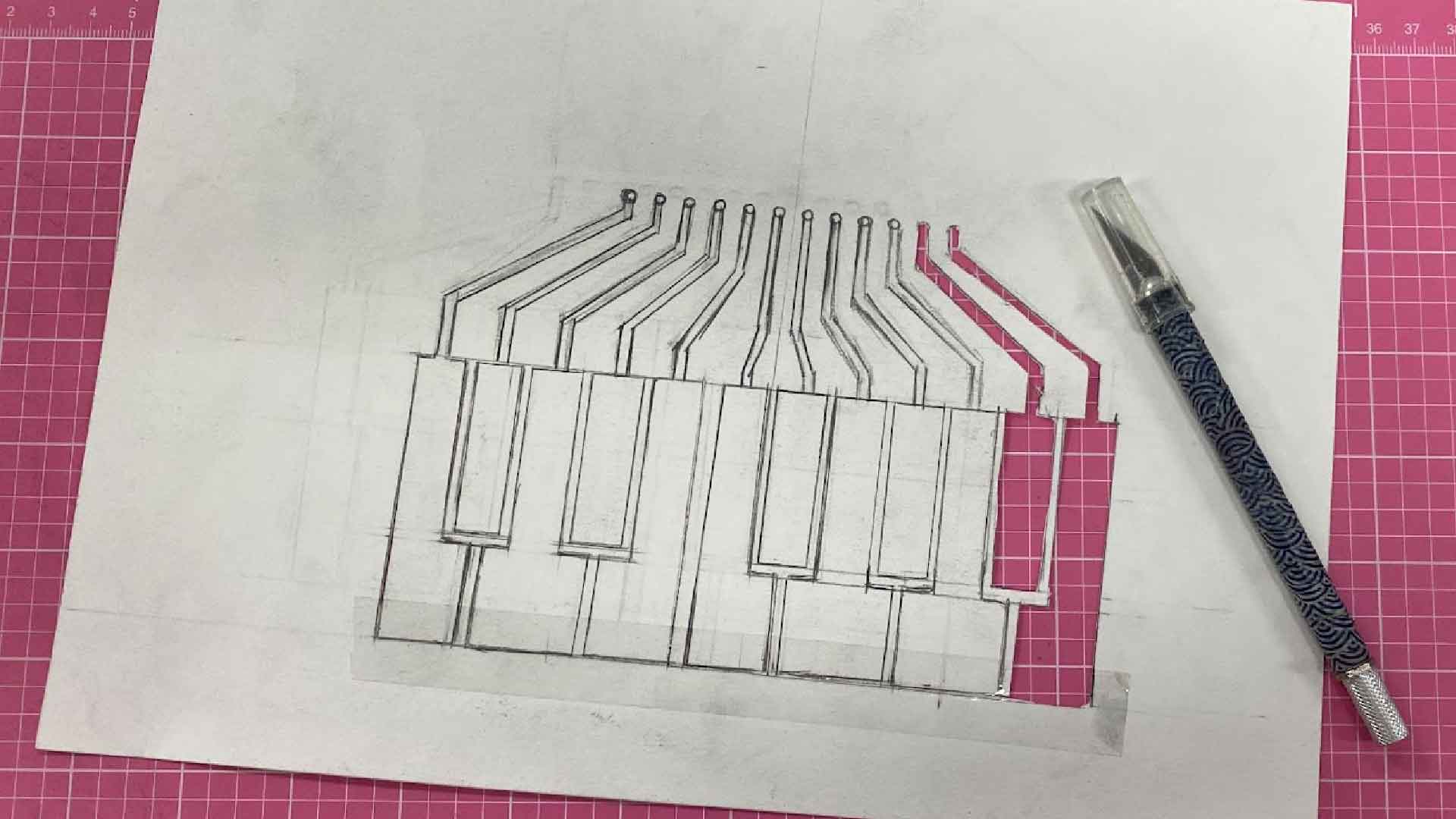
Freehand Drawing
Step 04 — Painting
The sketch was scanned and printed on printer paper. Instead of making a stencil, I decided to paint directly onto the paper.
My goal was to avoid painting the lines too close together and to avoid smudging the paint to prevent a short circuit.
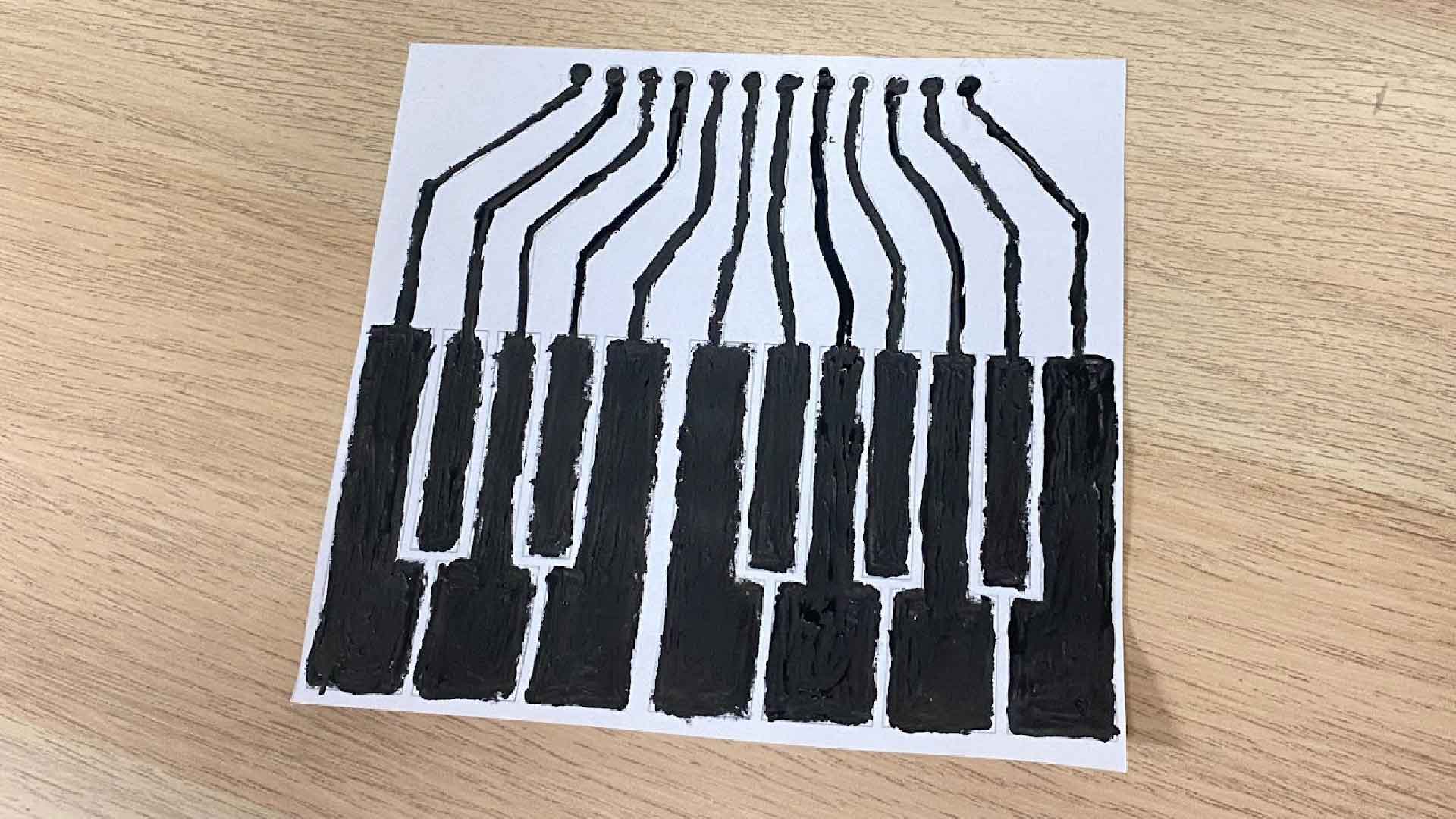
Painted Sensors
Step 05 — Testing with alligator cables
For testing purposes, I connected the alligator cables to the sensor and played my audio files before cold-soldering the touch board with paint.
As the last electrode failed to work properly during my first attempt, I believe I did not make an even paint surface, or perhaps I smudged the connection lines. My repainting has now made the paint surface more even, so the sensors are now working. I should normalise the volume levels of all my recordings next time.
Conductive Sensor Experiment
Due to the failure of my previous experiment with the electric paint sensor last week, I attempted another method for the bare conductive touch board. Due to the fact that I did not spray any fixative on the sensors, after pressing them multiple times the paint began to rub off. In order to conduct this experiment, I used aluminium foil tape as a sensor. I cut the aluminium foil tape into 12 rectangles and attached them with alligator cables in order to attach the sensor to the touch board. In my opinion, I prefer to use a conductive material as a sensor since it provides a more polished appearance.
Reflection — Messy cable connections
Since I do not need to worry about the surface
finish of the sensor, I have found conductive
sensors work better. I would like to hide messy
wiring from the user by creating a enclosure.
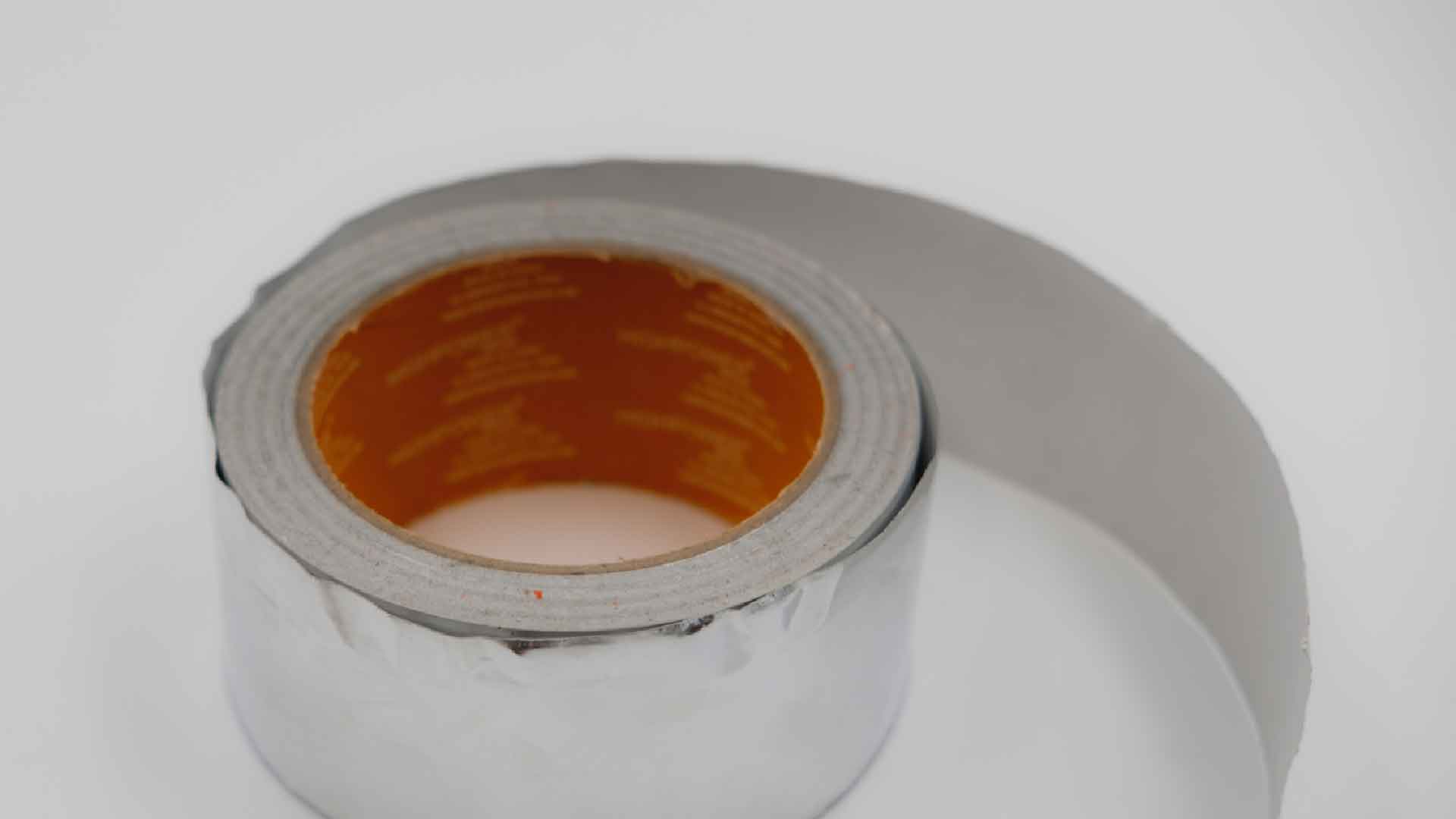
Aluminium Foil Tape 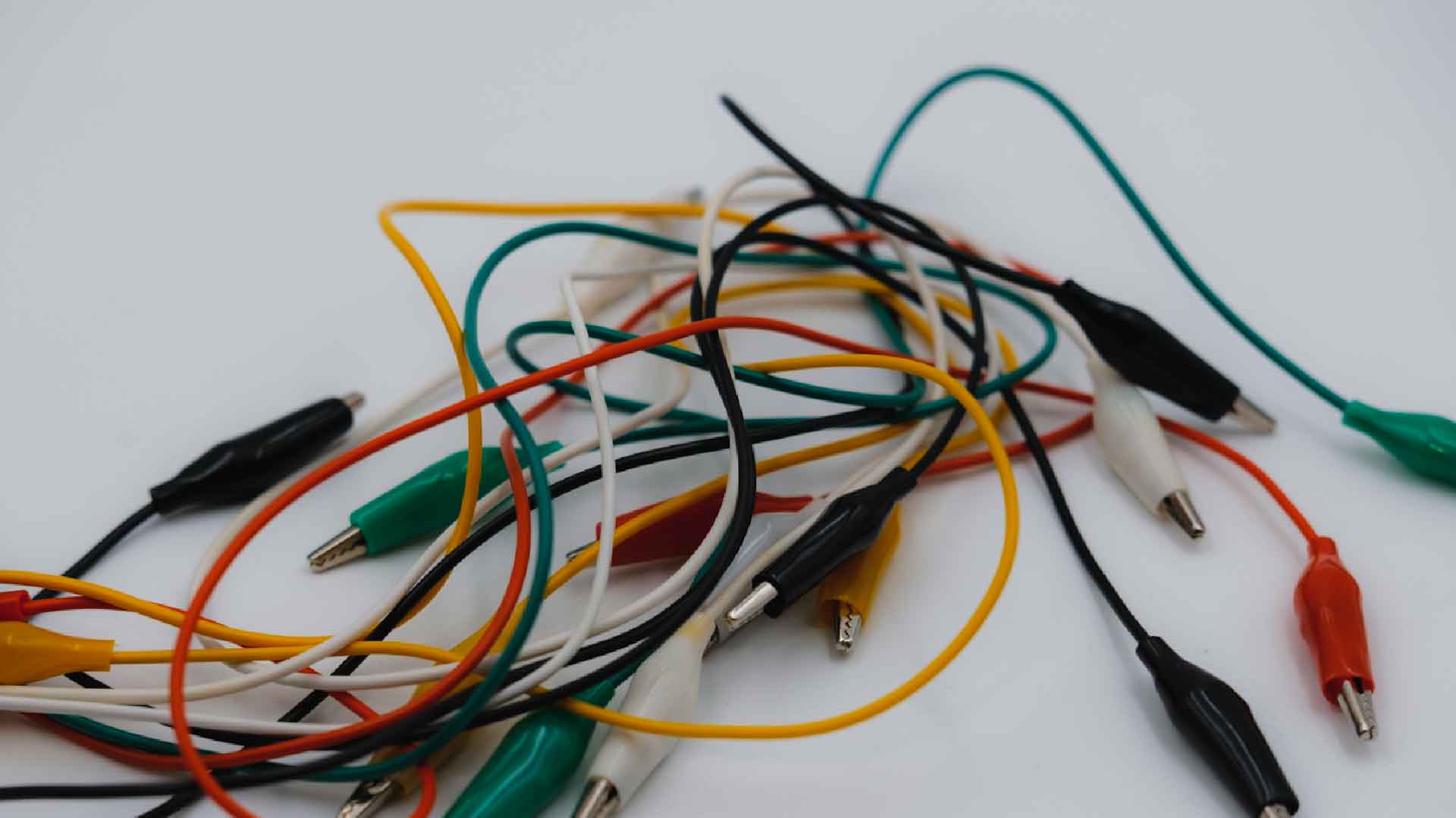
Alligator Cables 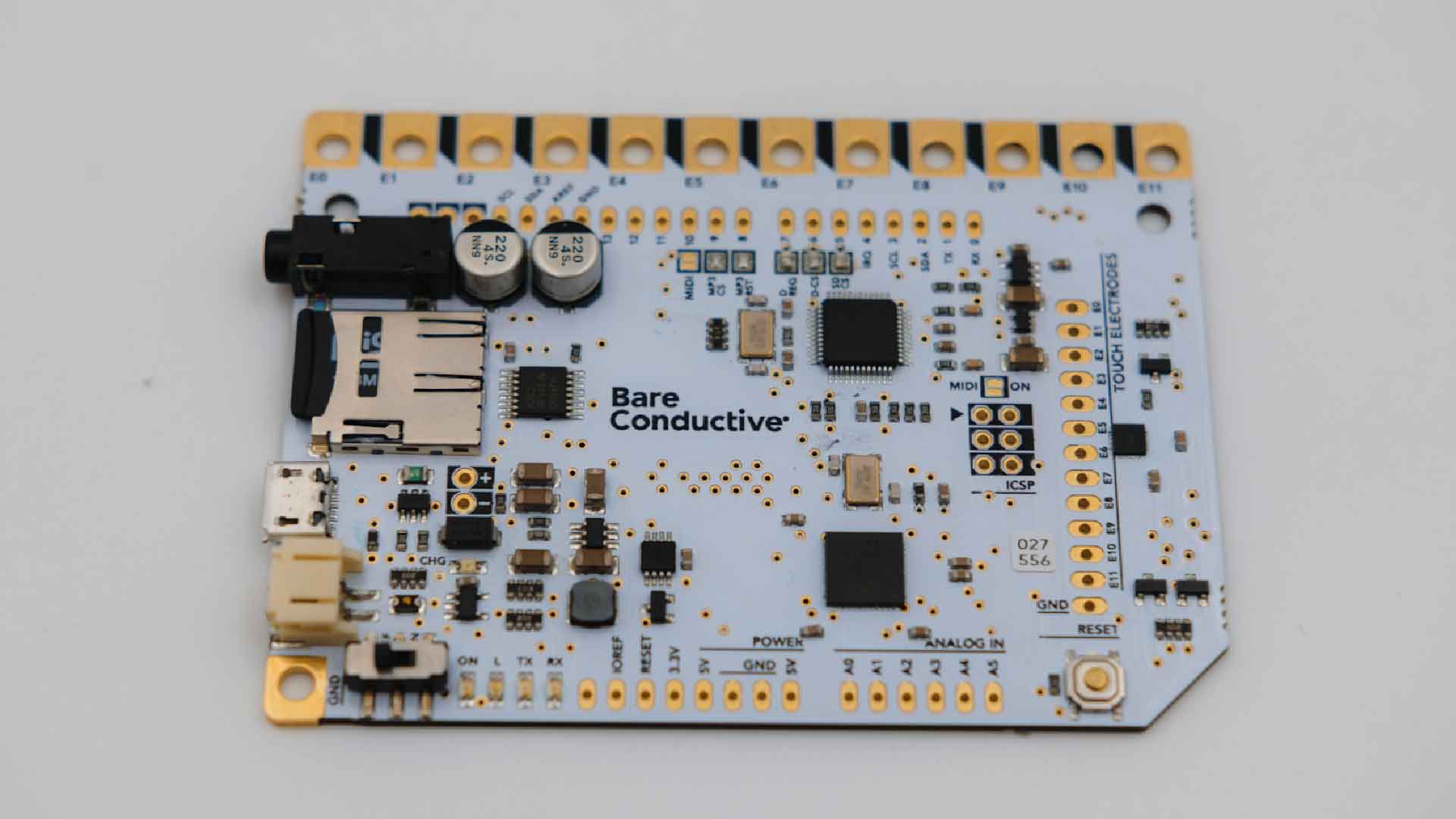
Touch Board
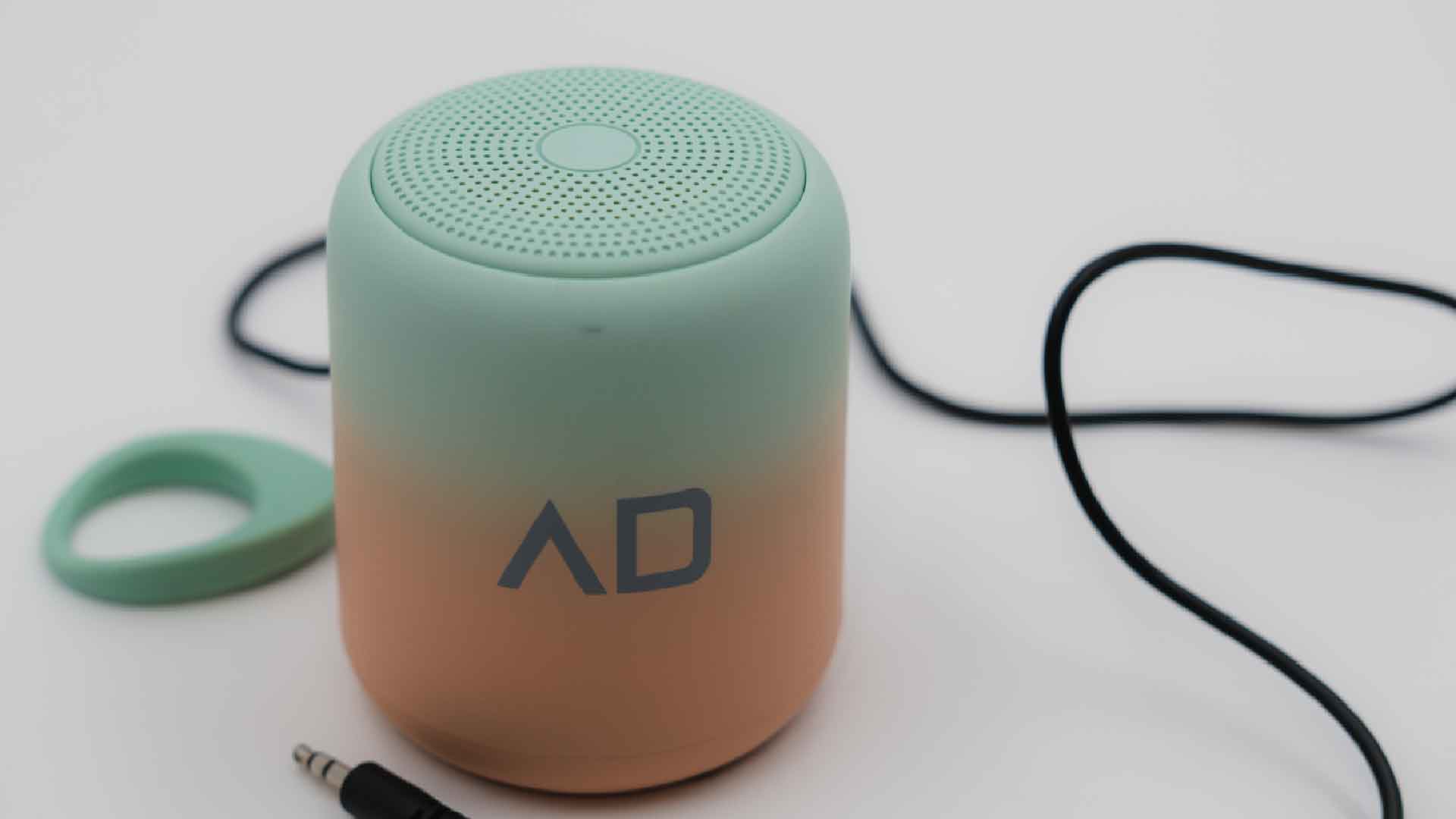
Speaker 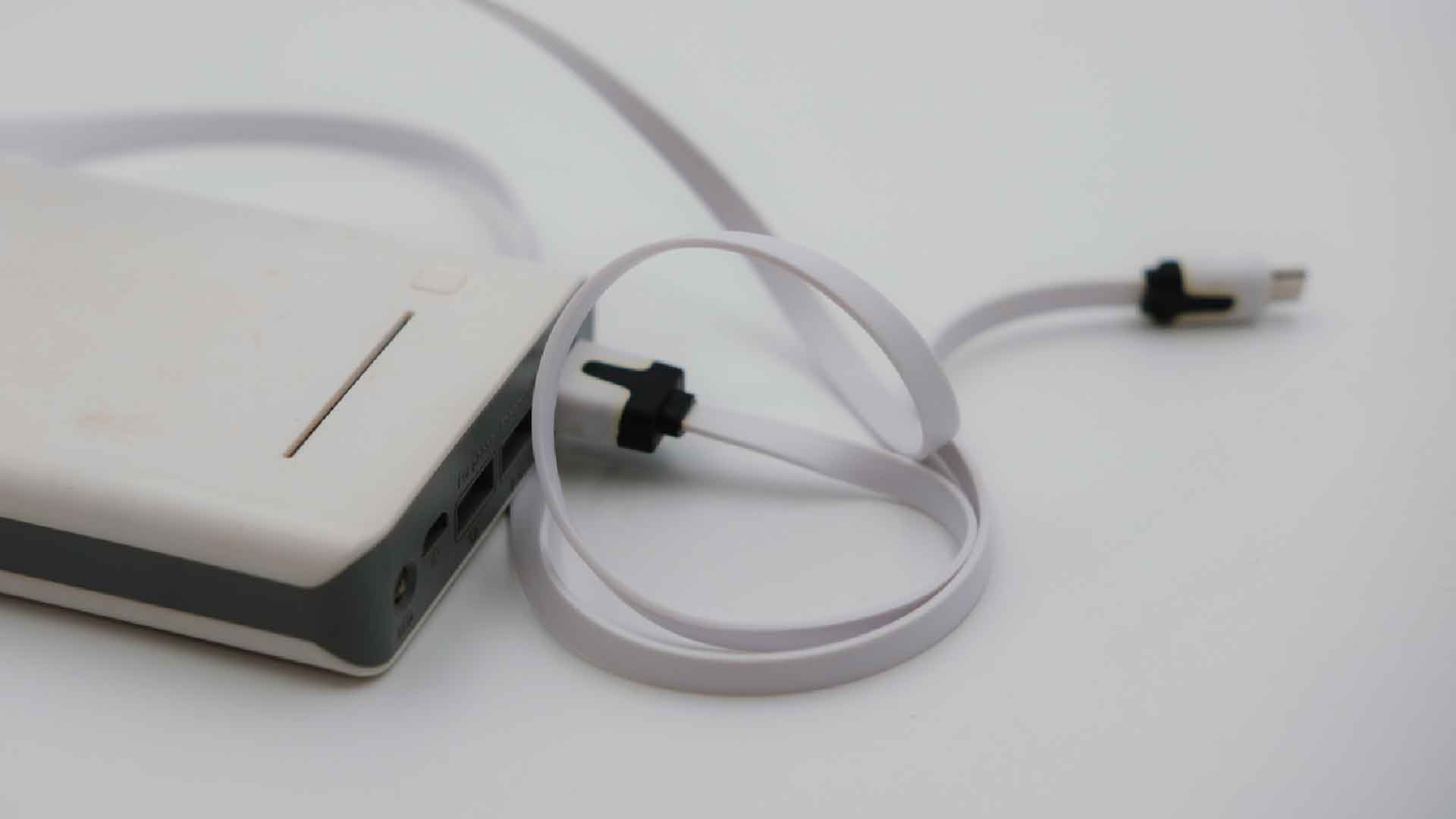
Power Bank 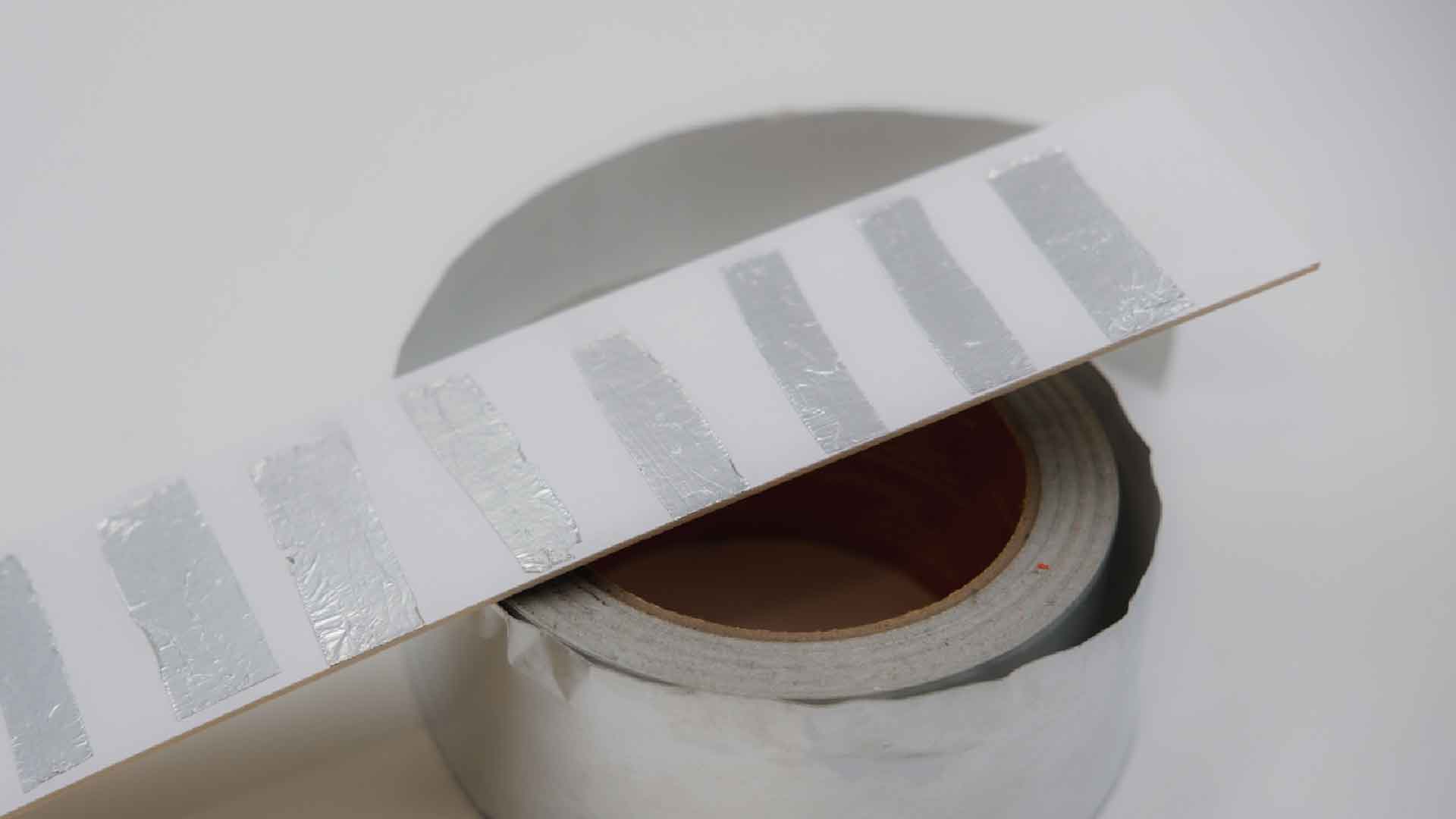
Conductive Sensor
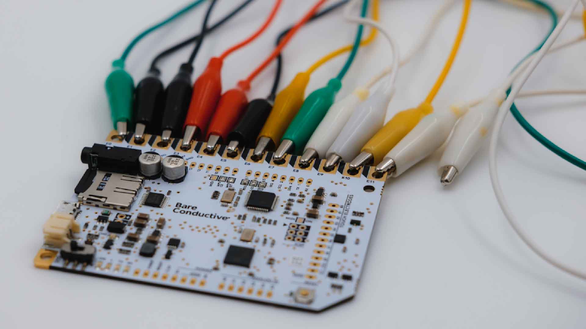
Connecting Cables 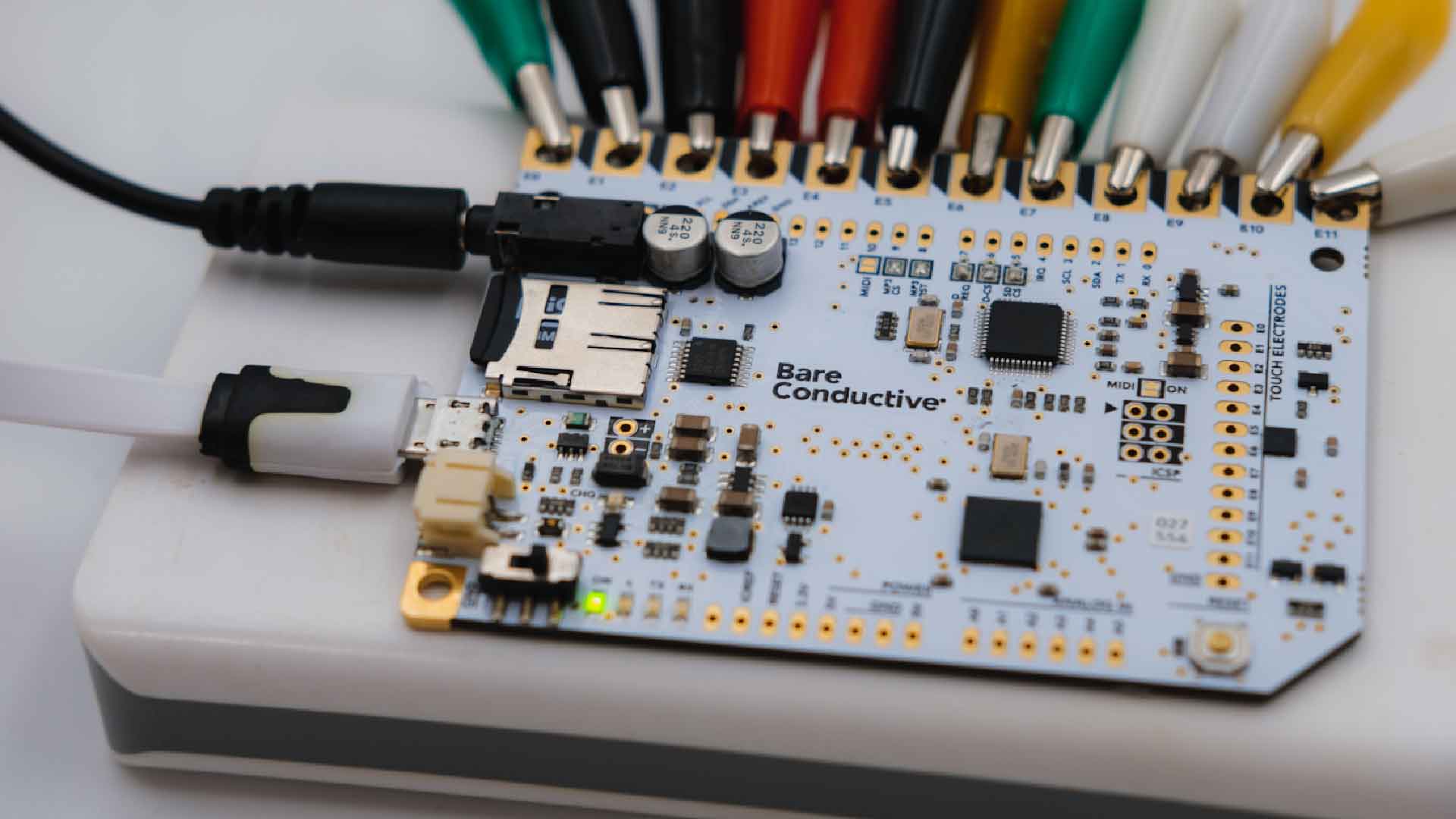
Powering The Touch Board 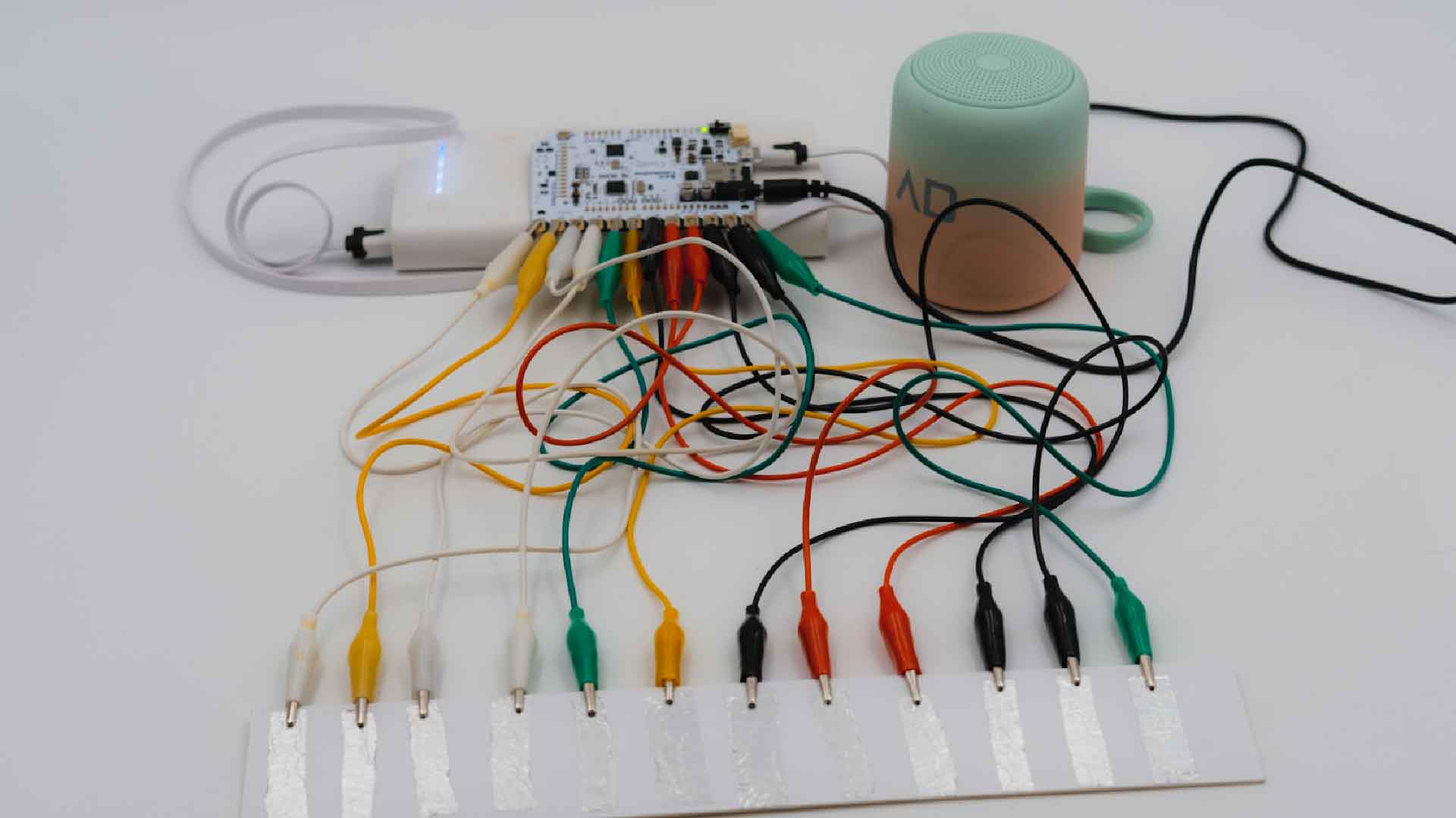
Conductive Sensor Experiment